Learn how computers work by building a retro game console

Retcon design revisions
Somebody stop me!
The latest PCB prototypes have gone off to manufacturing, the parts are all on order, and when they get back I’ll put them together and start filming some real demos and get the campaign back on track.
Here follows a walkthrough of what has changed.
Note: I'll post 3D pictures initially, and replace with real photos when the boards arrive!
Health warning: some technical talk follows – don't be put off by it, this project is still aimed at everyone!
Retcon AV: bye bye CPLD, hello modular core!
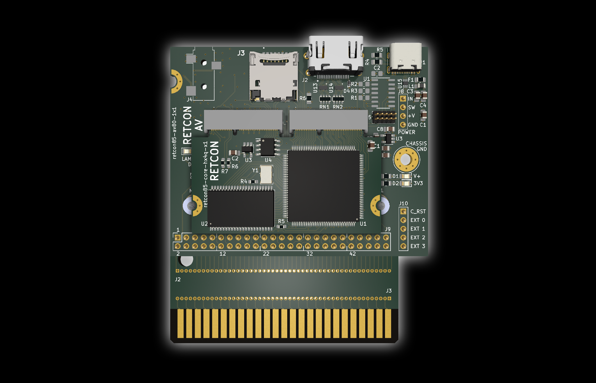
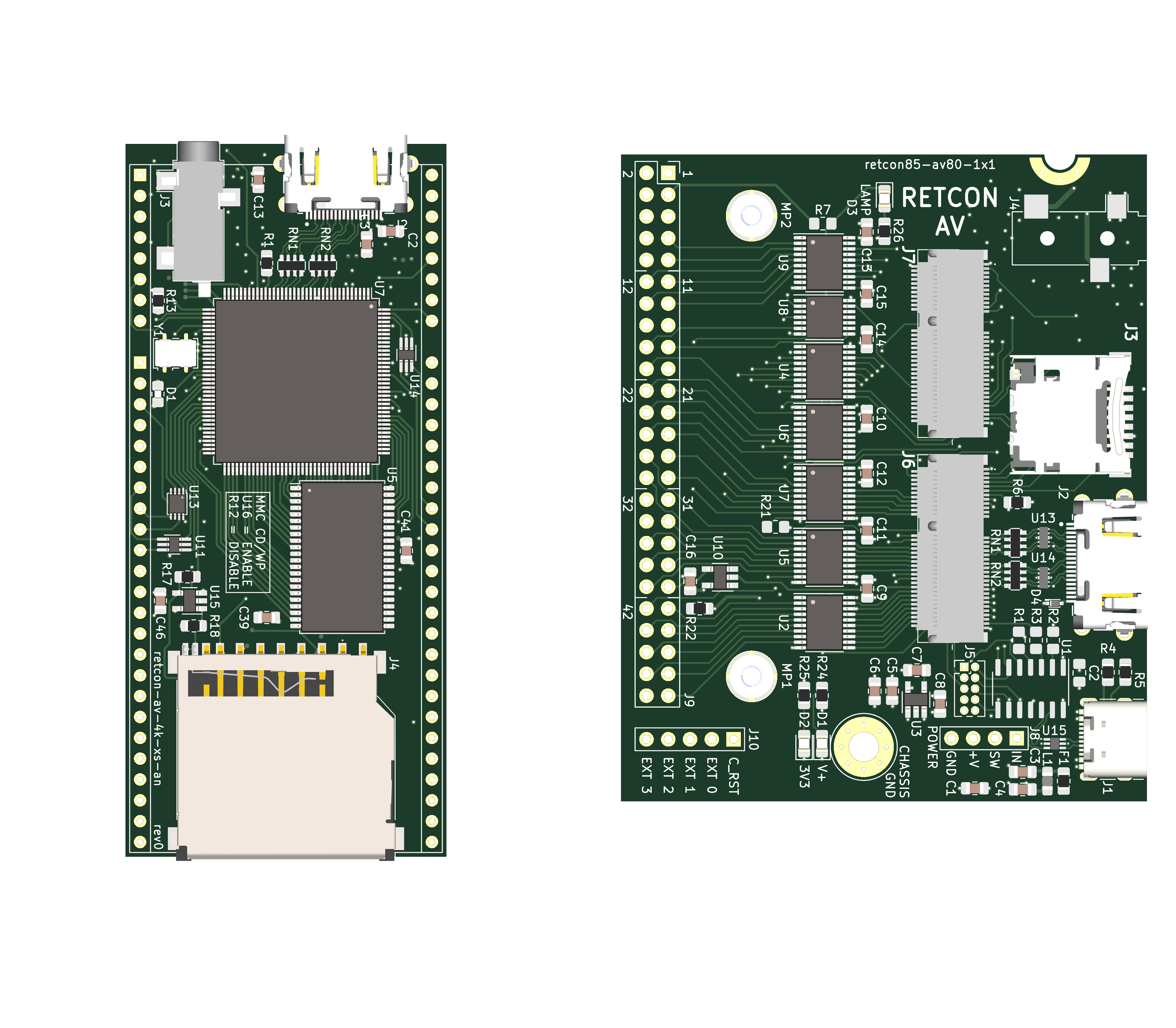
The biggest changes have been to the “Retcon AV” module which handles all the graphics and sound, and the changes were initially driven by supply problems. I originally had a single CPLDopen_in_new chip which translated voltage levels between the 3.3V FPGAopen_in_new and the 5V retro world outside. These chips are increasingly very hard to source and also prohibitively expensive and what’s more they aren’t even a particularly perfect solution when the number of I/O pins needed is larger than a single CPLD can provide. After struggling hard to make it work (during which time I fried a bunch of expensive chips!), I decided to go back to basics and use good old fashioned standard logic devices to do the voltage translations. This means higher chip count, but actually lower overall cost compared with the CPLD option, and it also means that it’s much easier to set up and use the module. It’s possible to get much smaller form factor standard logic devices too, so a future miniaturised redesign is still a possibility.
Also driven initially by sourcing problems, and the possibility of making the system more expandable, I moved the core FPGA, static RAM and companion devices out to a custom-designed micro module which slots into the main AV board. Having the AV board split into a core and carrier module means that it should be possible to design different core variants to flex around future supply issues or to take advantage of cheaper alternatives without having to redesigning everything. It also means that project creators should be able to mix and match capabilities more flexibly, even allowing them to design their own custom carrier boards for their own needs. As a bonus, if either the core module or the carrier board happen to receive damage, only the damaged item need be replaced, making repairs cheaper and more straightforward.
As a result of the above, Retcon AV is now slightly larger, and has a single 50 pin connector instead of two rows of 24 pins. I originally designed the AV to be the same size as one of the “module” slots on the project main board (although it turned out longer than a normal module in any case!) and I also thought people might want to plug them into solderless breadboardsopen_in_new. Although that was somewhat useful when I was developing the board, it turns out that it’s a bit of a pain plugging such a big device into a solderless breadboard, and having rows of pins on both sides made board layout, in particular placing the I/O sockets, more difficult. The main Project Board was always designed to be roughly compatible with PC ATX casesopen_in_new, since it’s as close to a common computer mounting standard as there is, and this change allows all of the I/O devices like HDMI, USB, 3.5mm audio jack and SD card to sit on the back edge of the board together, which is much more sensible than before, and inline with the ATX "I/O shield" positioning.
As you might also guess from the above diagram, I’ve also taken the decision to replace the full SD/MMC card slot with a micro SD card slot, which saves some space. What might less obvious is that I've replaced the mini USB connector on the main Project Board which was originally used to power the system with a USB C connector on the AV module instead. Both these changes were driven by feedback about what connectors and devices most people seem to have readily to hand. Full size SD, although still available and popular for digital cameras, are feeling more and more niche; and mini USB is very hard to find cables for now. Even micro USB's days seem to be numbered. The USB C connector should also theoretically pave the way for higher power draws in future, although the current demo Master System build is extremely low power and the older USB connector used before easily supplied enough current within a single USB load limit.
I had previously designed AV alternatives with both full size HDMI and micro HDMI connectors and I’ve scrapped the micro variant completely. Feedback shows that most people seem to really dislike micro HDMI, cables are uncommon and relatively expensive, and between you and me those teeny tiny connectors are a nightmare to layout on a PCB – and don't even get me started on how difficult they are to hand solder!
Loads more features have been added to the Retcon AV around future expandability, and I’m now bringing out every single I/O pin the FPGA has to offer, while the module connector has room to allow dozens more if a denser core is plugged in so that’s one less thing I’m losing sleep over. I personally think the new board is very handsome — the proportions are nicer and it feels more robust. That said, there are two features I am leaning towards removing: I had designed in a pretty decent DACopen_in_new with headphone amplifier and a 3.5mm jack for stereo audio out and I haven’t really used that feature at all — preferring instead to send audio straight through the video interface to the TV. The parts here really drive some cost, so instead I think I’ll end up offering an audio output as an optional expansion — either as a separate variant of the carrier board, or as a solderable module for you to add. A similar process is happening around the USB-enabled microcontroller (μC)open_in_new I had on the board — I just haven’t found it that useful, since it’s easy enough to reconfigure the board directly with an SPIopen_in_new interface or even with an SD card. The microcontroller isn’t particularly expensive, but for a part that isn’t used much it felt excessive. At the moment I plan to leave the board layout for it in place and connected to the USB C receptacle for those enterprising creators who feel like playing around with full USB support (limited to USB 2.0) in their retro projects and don’t mind soldering a few SMD parts.
What would you like to build today?
The other HUGE and incredibly exciting change to the Retcon design is around making it more system agnostic. The original Retcon design was inspired by the Sega Master System, which is — and I still believe this to be true — possibly the easiest retro console to clone. However there are loads of other projects that should be possible and there are other systems out there with significant fan bases that could be serviced. The original design, although theoretically not being opinionated was, in reality, very tailored towards the Master System at the expense of other systems, so in this latest design I’ve attempted to remedy that as much as I possibly can.
The main Project Board, which previously had a silkscreen specific to the Z80 and even a few signals specific to the Master System, has now been made generic. There are still up to 9 general purpose “module” slots, but now these have a coordinate numbering system which still allow easy wiring instructions in tutorials but which avoid any confusion when non-Z80 systems are being designed.
Correspondingly the I/O of the AV module, which was previously designed mostly with the Z80 and Master System in mind, is now arranged more generically into a number of “ports”, each of which has different capabilities like bidirectionality, tristate and open drain outputs; a little bit like PIAopen_in_new chips of old. It’s a relatively small change, but makes a huge difference when it comes to building different systems.
Of course, retro gaming wouldn’t be complete without cartridges, and this next change is one of the most exciting. The first Retcon Project Board had layout for a hard-wired Master System cartridge slot, which worked well enough and saved some wiring, however it was of no use at all for those wanting to clone other consoles. Even something like the Atari 2600, which uses a similar pitch and smaller cartridge that ought to fit in the same pin layout wouldn’t work in the Master System slot position because of the hard wiring. Some of you may be aware that I was playing with the Sega Game Gear replacement cartridge slot from RetroSix, and managed to hack that onto my Project Board and actually get Game Gear games running on my TV! However the result was not particularly pretty and was a pain to wire up. Finally, I really would like to make a NES clone. Contemporaneous with the Master System, the NES also uses mostly stock parts and aside from a slightly different approach to the cartridge bus, it ought to be possible to build, but again the cartridge is a problem. In their infinite wisdom, Nintendo used a non-standard 2.5mm pitch cartridge format, which means you can’t just go down to your friendly electronics dealer and buy a compatible slot. What you can easily find though are aftermarket replacement slots, which are designed to be mounted onto the original NES main board. Still, at 2.5mm pitch these require a custom PCB layout.
Enter the “Retcon Play3” board — a double-width expansion module that slots into the Project Board alongside the AV module and provides the opportunity to connect at least 3 different types of cartridge. It’s got space for an up to 60 pin 2.54mm pitch connector which could accommodate the Master System slot, older Sega consoles like the the SG-1000 or Mark III, Atari consoles like the 2600 or 5200 and — at full stretch — the Famicom. And – you guessed it — I only went and put a 72 pin 2.5mm card edge on the back of the board which accepts the NES replacement cartridge slots, making playing original NES cartridges a real possibility. The geometry is such that the cartridges would front-load, like in the NES (and unlike in the Famicom).
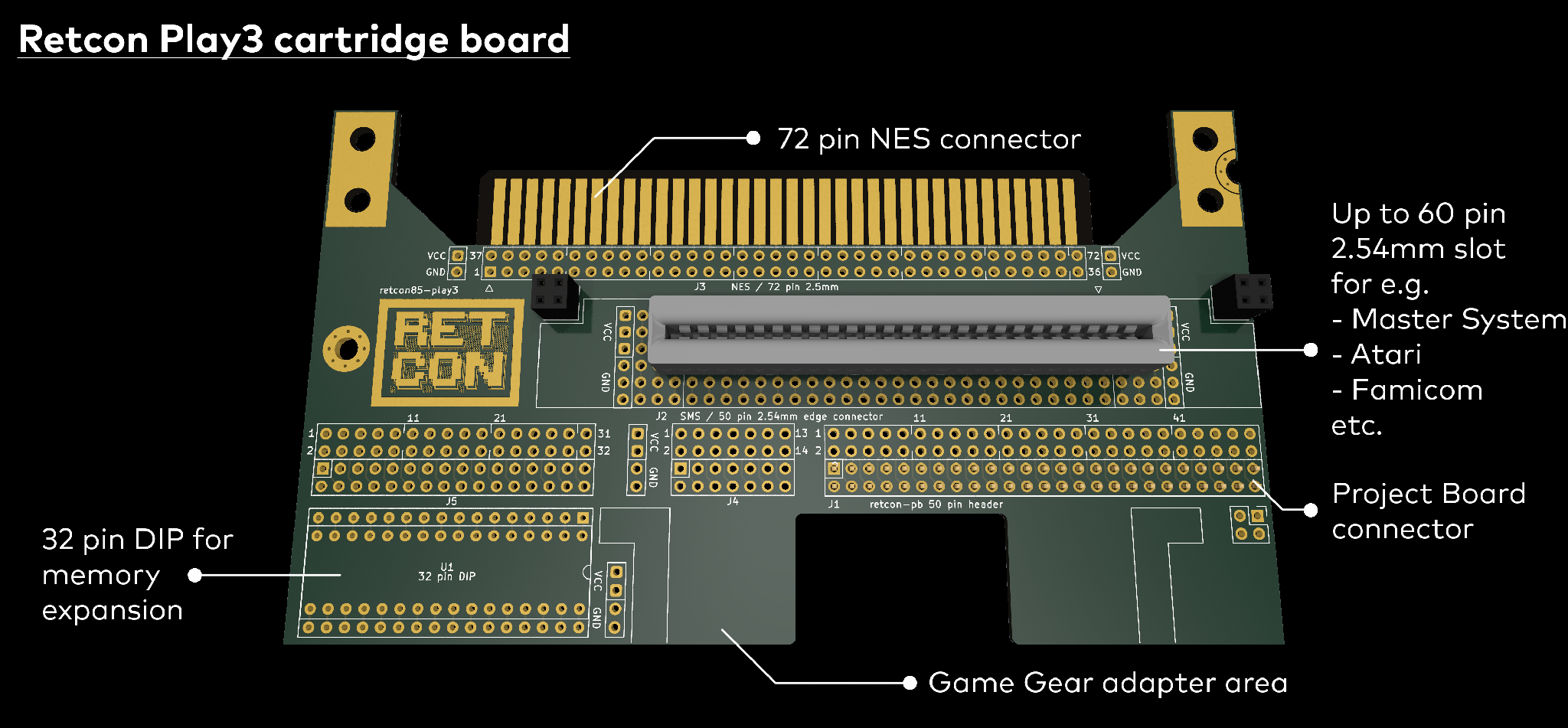
I’ve also designed an optional adapter board that accepts the RetroSix Game Gear cartridge slot kit either as supplied in two part form, or as just the cartridge slot for those who want a slightly neater finish and who don’t mind soldering an FFC socket in place. The Game Gear adapter doesn’t interfere mechanically with the 2.54mm socket when mounted vertically, so it should be possible, for example, to build a system which can accept both Master System and Game Gear cartridges, as I have already proven with the original Retcon boards. It's also possible to mount the Game Gear adapter horizontally, but this prevents other cartridges from being inserted in the 2.54mm area.
The Play3 board has no hard wired traces, which means that you have to do a little more manual wiring, but now it should be possible to build systems compatible with many more cartridges.
Finally, the Play3 board has space for one additional 32 pin DIP device, meaning it could host another 512KB of RAM or ROM for example.
Project Board improvements + smaller board
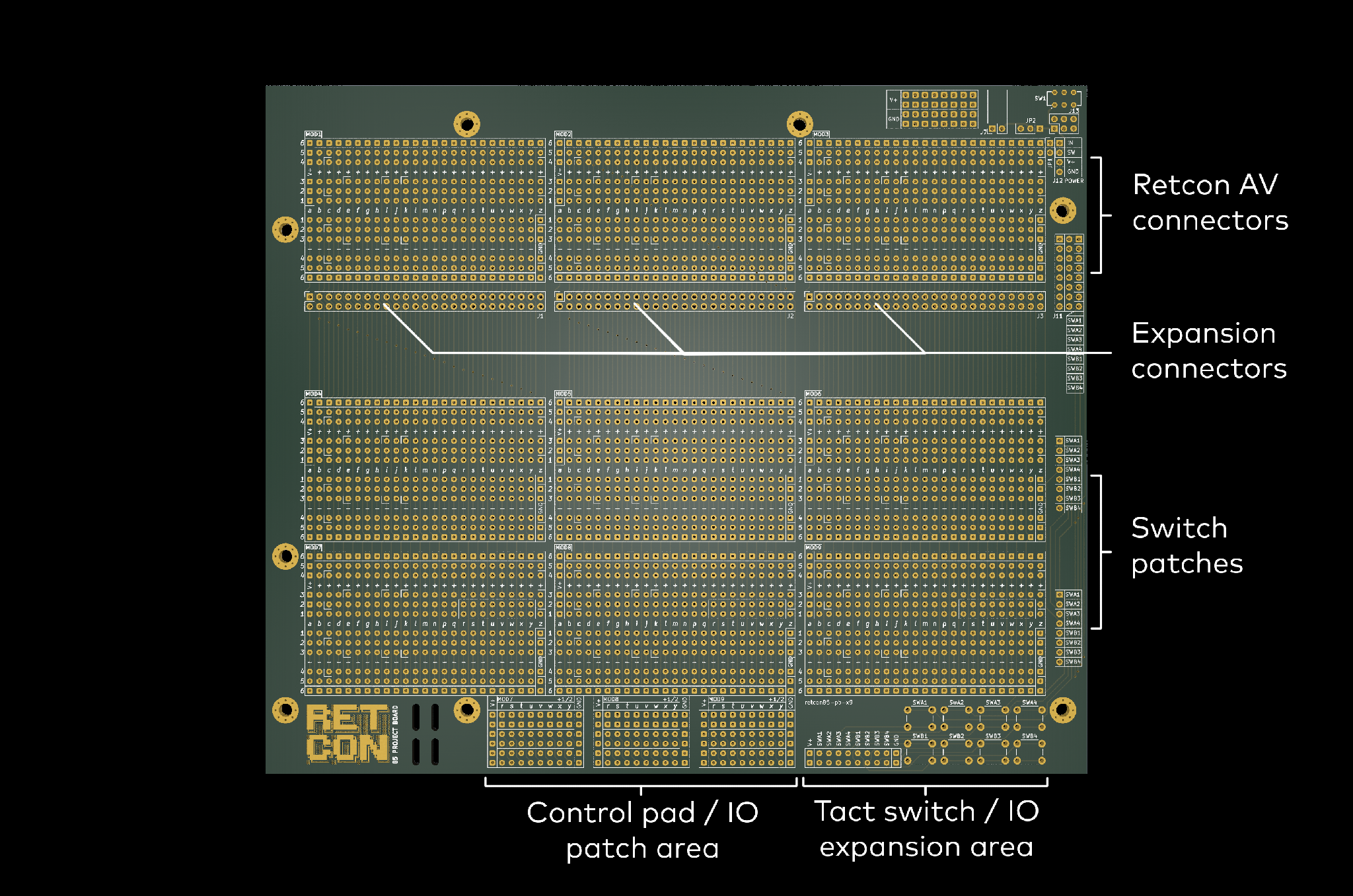
All the above changes to the Retcon AV and the introduction of the Retcon Play3 necessitated some adjustments to the main Project Board. One thing that always bothered me was the portrait orientation of the original board, since it’s just so unusual to see a retro console — any console for that matter which is narrower than it is long. It turned out that flipping the board on its side solved a few problems, so that’s now done and the original 9 module slot board fits into a footprint that’s approximately the same area as before, but in landscape aspect, allowing the full width of a single module for I/O to project from the top edge of the AV board as well as putting the cartridge slot slightly more central than the old design where it was right on the rear edge.
In keeping with the other changes to make the Project Board less opinionated, the hard-wired front patch panel which was designed with the Master System control pads in mind has been made more generic and also expanded in area. Now the bottom three module slots (7, 8 and 9) each break out 8 pins to the controller patch panel for a total of 24 pins available for general I/O at the front of the board. The original board had positions for 4 tactile switches on the front of the board, with breakouts for a few choice Master System specific pins to connect to, whereas the new design now supports 8 such switches and allows any (or none!) of them to be passed up the board, very close to modules 9, 6 and 3 and optionally into the AV module. The “standard” redesigned AV module described above can accept up to 4 of these switch inputs on a dedicated connector, or more via the standard 50 pin bus connector if necessary. As with everything else on the Project Board, there are alternative connectors to allow the switches to be mounted externally rather than using the footprints on the board if you prefer to build your own case.
More out of curiosity than anything else, I also designed a more compact version of the 9 module with only 6 modules. This brings the board size down to 217x142mm, which has, to my mind at least, more “classic” console proportions, at the expense of 3 useful module slots as well as breaking the ATX compatibility of the board. All the peripheral connectors remain the same, except with one fewer breakout for the 8 tactile switches, since module 9 is now not present.
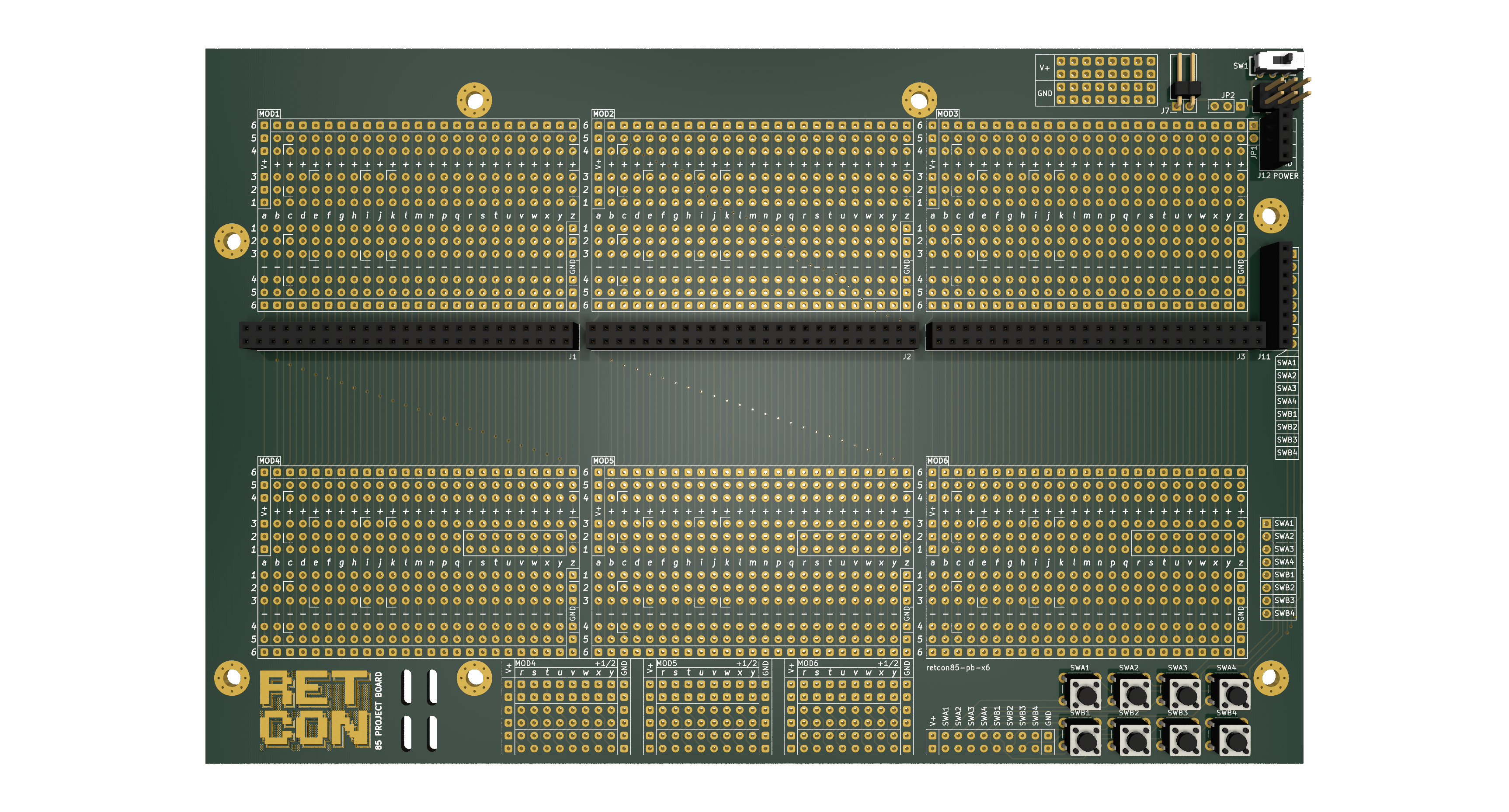
It should just about be possible to build the canonical Master System project with 6 module slots although it will certainly be much more cramped and some of the components will have to go underneath the AV or Play3 boards.
Introducing the Retcon Controller!
Last, but most definitely not least, I finally designed some Controllers to go with the system. After trying a few different alternatives for models, I found these gorgeous NES controller shells and buttons from Retro Moddingopen_in_new. They come in various colours and feel really robust with a nice weight to them and positive button feel.
So the controller boards I’ve designed will fit inside those shells and — I assume — by extension an original NES controller, although I don’t have one to verify that with. Since I don’t necessarily plan on reselling controller shells, I would leave it up to you whether or not you want to source your own, but if you don’t, the Retcon Controller PCBs also have space for 8 tactile switches to be mounted over the top of, and as an alternative to the membrane switches. This means you can operate your console with just the bare PCB controllers that come with the kit, which is good enough certainly for experimenting with the kit and for some casual gaming too, although tact switches don’t have the same feel as membrane ones, and won’t last so long with heavy use.
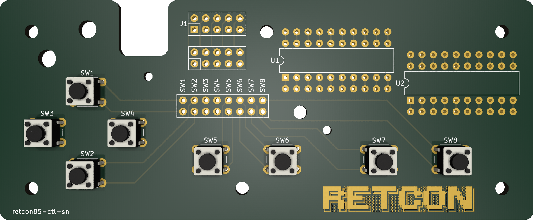
The Retcon Controllers have room for a 10 pin header, or direct cable connection, and if you’re using the Retro Modding shell it has cable strain relief built into the shell. 10 pins is one more than the Master System needs for its parallel controller interface (you could maybe use that extra pin for a pause button — like the Game Gear), and 3 more than the NES had in its 7 pin serial port, only 5 of which are needed for the standard controller. There’s room on the Retcon Controller PCB for two 20 pin through hole ICs, so building basic parallel to serial conversion onboard is an option.
Just for fun: an HDMI flashcart for the Master System?
One more thing, which is not necessarily part of the Retcon project proper, but one thing that came out of discussion of retro console owners is that the Retcon AV module could be used to augment original consoles with digital video and audio output. Also since it has enough I/O to handle all of most 8 bit processor buses with room to spare, and also has an SD card, it could be used as a "flashcart" for those so inclined. The combination of both of these things is potentially appealing, and so I knocked up a quick adapter board to allow the Retcon AV to be plugged directly into a Master System cartridge slot, to prove the concept of an HDMI output adapter in a cartridge form factor. Will see how that goes!